+86 177 5193 6871
222, Block B, Diamond International, Guozhuang Road, Xuzhou, Jiangsu, China
The coal handling project includes two space frame spherical shells, the structure form and size of which are the same, the structure type is the bolt ball joints are placed square pyramid spherical space frame, the lower chord peripheral point support, the support adopts one-way sliding support, the support The span is 124.35 m. The ground elevation of the project is +5.00 m, the elevation of the bottom of the support is 26.5 m, the elevation of the space frame top is 71.15 m, and the elevation of the skylight top is 74.15 m.
According to the characteristics of the reticulated shell of this project, the spherical reticulated shell is firstly installed with a starting unit to form a closed structure, and then the closed structure is used as a supporting system. The follow-up space frame is installed by using the method of ring-directed bulk small units. For this project, the above method is also adopted, that is, starting from the first ring (counting from the support, one space frame on the upper chord and one space frame on the lower chord in the height direction) adopt block docking, and then start from the second ring. The method of high-altitude bulk packing is bulk packing round by round until the installation of the entire spherical shell is completed.
3.1 Check calculation of starting unit before installation
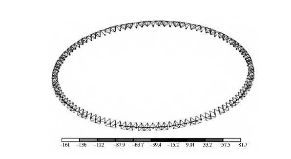
(1) Stress check calculation. According to the stress checking diagram (Fig. 1), the maximum stress of the starting unit is 161 N/mm 2 , less than 214.7 N/mm2 (design stress), and there are no overstressed components, meeting the design requirements.
(2) Stress ratio statistics. According to the stress ratio statistical diagram (Figure 2), the maximum stress ratio of the starting unit is 0.75<0.8 (the design allows the control stress ratio), which meets the design requirements.

Figure 1 Stress checking calculation
3.2 Starting unit installation process
The installation process is as follows: transition board installation → block space frame assembly → block space frame hoisting → block space frame fixation → block space frame aerial docking.
3.2.1 Adapter plate installation
(1) Preparatory work before installation: Before installing the transition plate, first check the supporting surface with a total station according to the cross line popped up by the civil engineering unit at the position of the embedded part.
(2) Installation of the transition plate: place the transition plate in place according to the edge line that pops up on the support surface , and perform temporary spot welding on the four sides of the transition plate . The welding length of each side is 100 mm . The support is fully welded.
3.2.2 Assembly of block space frame
According to the size of the reticulated shell , the height direction of each block space frame is one space frame on the upper chord , one space frame on the lower chord , six space frames on the upper chord , and five space frames on the lower chord in the circumferential direction . The reticulated shell has 36 axes in total . Each axis is divided into 1 block unit , which is divided into 18 block space frames of the same size in total. The block space frame is assembled on the ground as a whole . When assembling, install and fasten all the rods in place at one time . If there are screw holes that are difficult to install , use a tap to repair the screw holes and then install them to ensure the installation accuracy.
3.3 Hoisting of block space frame
3.3.1 The selection of the crane After calculation, the weight of the block space frame is less than 4 t, and the crane is selected according to the calculation of 4 t. According to the site conditions, the crane station is located outside the retaining wall. The crane is a 25 t truck crane from XCMG . 29.34 m is selected , the radius of gyration is within 12 m , and the lifting capacity is >5.6 t , which meets the hoisting requirements.
3.3.2 Selection of wire ropes for hoisting
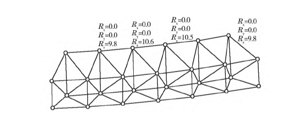
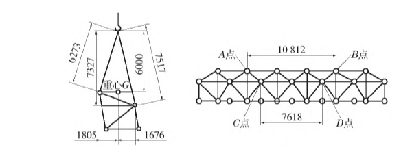
According to the suspension point reaction diagram (Fig. 2 ), the weight of the block unit can be calculated as 4 t. According to the size diagram of the block unit (Fig. 3 ), the height of the lifting point is selected to be 6 m from the lifting point A, and the length of the steel wire ropes at points A and B, and the length of the steel wire ropes at points C and D can be calculated. Then it is calculated that the tension on the wire rope at point A is 40/4/(6000/8281)=13.8 kN , point B is the same as point A; the tension on the wire rope at point C is 40/4/(7327/8426)=11.5 kN, D Point is the same as point C.

Figure 2 Reaction diagram of lifting point

Figure 3 block unit size
Calculate the steel wire rope type selection according to the force at point A, and consider the safety factor of 6 times, then the breaking force of the steel wire rope is 13.8×6=82.8 kN. According to the mechanical performance table of the steel wire rope, select the 6×37 series steel core steel wire rope. 1700 MPa, diameter ≥ 13 mm.
