+86 177 5193 6871
222, Block B, Diamond International, Guozhuang Road, Xuzhou, Jiangsu, China
2、Space frame installation
2.1、Overall program overview
(1) Construction process flow construction preparation → foundation review → ground assembly start space frame → block lifting → closing → correction → small unit lifting → correction → bearing welding → painting → acceptance.
(2) according to the construction site situation, develop the space frame lifting program technology research and development center and installation center and construction team leader to determine the location of the lifting point, technology research and development center designers according to the location of the lifting point provided, the lifting force analysis of the node bolt ball, high strength bolt, rod at the location of the lifting point, if found that the bolt ball, rod, high strength bolt can not meet the requirements of the force change at the lifting point, should be replaced in a timely manner before the processing of the components, to ensure that the force change in the location of the space frame structure to meet the lifting safety requirements when the site lifting.
(3)Before the installation of the bolted ball node space frame, the elevation and axis of the supporting surface were carefully reviewed and the drawings were recorded. Firstly, the starting space frame was assembled in blocks on the ground, and then six 130T automobile cranes and one 50T automobile crane were used for aerial docking to form a stable structural unit. After forming a stable structural unit, the starting space frame was used as the basis to install the bulk of the space frame on both sides by using the overhead bulk method of assembling and pushing triangles. After the start frame is installed separately, the elevated frames at each end are installed separately by the aerial bulk method.
(4) The starting space frame adopts the ground block assembly crane aerial docking and collocation installation construction method. The main point of the starting space frame construction is that the starting space frame supports the upper chord ball in the column top support rotation, so that one end of the block starting space frame to support the upper chord ball as the axis of the other end in the crane upward traction role of the rotation of lifting, until lifting to the design elevation position for collocation assembly.
2.2、Assurance measures
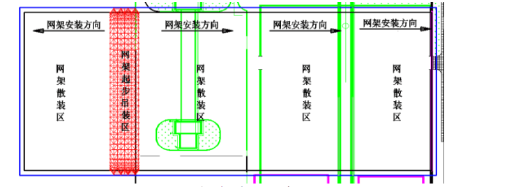
Because the project site 11 axis-14 axis for the car coal unloading ditch, 25 axis-27 axis for the coal conveyor bucket wheel, and the project schedule task is tight, after the site survey only 7 axis to 9 axis area to meet the ground overall assembly and lifting machinery station space, after the study decided to first 7 axis line – 9 axis line to start the installation of the space frame, that is, the starting frame installation, construction is completed to 1 axis line and 32 axis line on both sides at the same time, so that the original side of the work surface into two sides of the work surface, improve the construction efficiency, the schedule can also be guaranteed, while reducing the structure construction errors.
(1) Management measures: before the installation of the space frame, technical training for all construction personnel, a comprehensive technical briefing on the installation of the space frame. The technical person in charge of the project and full-time safety personnel in the process of the installation of the space frame at any time, according to the special construction program, construction drawings and relevant documents, specifications for on-site inspection, found problems immediately notify the space frame operation team to rectify, and the implementation of rectification. Each process of the more dangerous parts of the project should be accepted before implementing the next process.
(2) Organizational measures: select project management personnel with rich experience in construction of similar structural forms of space frame for construction management, and preferably select construction teams with rich experience in installation of similar space frame for actual operation of space frame installation, so as to ensure that the installation can be carried out strictly in accordance with the construction drawings and special program requirements to ensure construction quality and safety.
(3) Technical measures: Strictly follow the relevant requirements in “Code of Construction of Steel Structure Engineering” GB50755-2012 and “Code of Construction Quality Acceptance of Steel Structure Engineering” GB50205-2001 for construction inspection and calculation, so as to ensure that every data of the space frame installation is well documented and technically ensure the safety of the space frame construction, the following figure for reference.

Figure 2 Space frame installation plan layout

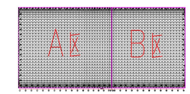
Figure 3 Space frame installation partition layout plan
2.3、Space frame installation scheme
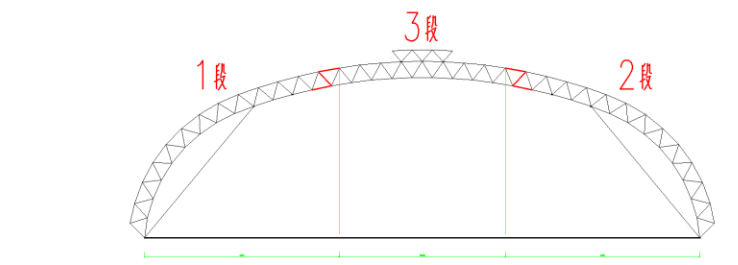
(1) This project adopts the space frame A area 7 axis – 9 axis as the starting area of space frame construction, the starting area first span installation when the focus of the project, the difficult point. Before the installation of the first span, it was preassembled into 3 sections on the ground (the purpose of dividing the space frame into 3 sections is to avoid the highest point when docking in the air and increase the safety factor) when assembling two 42.5m and one 35m span space frames on the ground.
(2)Using four 130T automobile cranes to respectively place the two sides of the 2 sections of the space frame support bolt ball in the space frame support body, using round steel to wrap the bolt ball in the support body, the crane for structural lifting, segmental starting space frame to support the body as the center of the circle, space frame support ball in the column top support body rotation, both sides of the 2 sections of the space frame in the crane upward traction under the role of the support body as the center of the circle rotation lift, lift to the design elevation position.
(3) Using two 130-ton cranes to lift the middle segment to the design elevation position, first docking one side of the segmental space frame, docking is completed, the other side of the segmental space frame to adjust the position of the combined assembly, structural docking is completed, the crane slowly unload, observe the starting space frame structure without structural deformation after the starting area space frame to form a stable structural unit, the crane unload.
(4) A area 7 axis-9 axis, aerial docking method completed, the rest of the area using crane lifting vertebrae 1 axis and 18 axis on both sides of the extension for aerial bulk method, and then use the aerial bulk method to install the two ends of the mountain wall space frame, until the space frame installed.

Figure 4 First span installation schematic
(1) After the installation of the A area, the B area 19 axis – 20 axis line using the connecting rod construction method for installation; B area space frame construction to 25 axis line structure ready for 25 axis line – 27 axis line across the doorway installation, B area space frame installation to 26 axis line doorway installation using a 50-ton crane, as a temporary support for the space frame structure here (to maintain the lifting point in the design position or slightly below the design position within 100mm).
(2) The installation steps of the mountain wall space frame are similar to those of the roof space frame, also the corresponding cone is put together on the ground first, and the 25T crane is used to gradually start from one side to the other for overhead bulk installation.
(3) expansion joint location of the space frame installation using expansion joint connection construction method for installation, expansion joints at the upper and lower chord of the space frame bolt ball in the drawing deepening increase hole diameter M20 rod connection holes, both sides of the space frame connecting rod with a diameter of 114mm steel pipe, processing plant into the form of space frame rod, the overall length of the rod than the theoretical size of 3-5mm less, convenient for later dismantling and reuse.
(4) After the installation of the space frame is completed, purlins, roof panels, catwalks and other facilities can be installed.
