+86 177 5193 6871
222, Block B, Diamond International, Guozhuang Road, Xuzhou, Jiangsu, China

Figure 1 Steel Tensile Membrane Structures for Bleacher Roofs
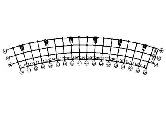
The stadium membrane structure is a cantilevered canopy structure, which adopts a tensile membrane and space steel pipe structure system. The joints adopt intersecting welding joints, and the building plan is shown in Figure 2. Inner ring and outer ring are concentric arcs with an outer ring radius of 223m and arc length of 138.24m, an inner ring radius of 207.5m and arc length of 128.63m, and an overhang span of 17.488m. There are 18 trusses in total, with different angles between each truss. There are 12 reinforced concrete columns at the end of each truss. The ends of 6 trusses are supported on the reinforced concrete columns by two arches at the front end of the lower part of the truss and one arch at the rear end. The elevation of the cantilever end is 16.1207m, the elevation of the cantilever end is 25.096m, and the relative height is 8.976m. The end of the cantilever is connected through a long connecting beam, and the supporting part is connected with the trusses on both sides by an arch. The overall stability of the cantilever is guaranteed by the connecting beam at the end, the bending beam between two trusses, the connecting beam in the middle, the tie rod, and the cable at the front.

Figure 2. tensile structure stadium plan
Adopts two kinds of calculation models to analyze the tensile membrane structures, after the first model will find the shape of the membrane in counteracting forces produced by the loads for the load imposed on the skeleton structure, ignore the interaction between membrane and the skeleton, and the load analysis of membrane using nonlinear finite element program is compiled, skeleton part adopts large general finite element program Ansys analysis; In the second method, the cable membrane roof after shape finds is integrated with the skeleton structure, and Ansys is used to analyze the displacement and internal force of the structure under the action of dead weight, pre-tension, dead load, wind load, snow load and so on. The membrane unit is shell 63, and only the characteristics of the membrane are considered. The Beam unit adopts BEAM4, the rod unit adopts LINK8, and the cable unit adopts Link10. All the main stress components of the cantilever are round steel tubes, made of Q235 steel, and the pull rod is round steel and made of Q345 steel. The upper and lower strings and the arch of the truss are continuously connected. The belly rod is welded with the upper and lower strings and the arch. The bearing is connected to the reinforced concrete column by high-strength bolts, and the bearing is assumed to be hinged. Truss on the bottom chord and intermediate CHS, arch, with space beam element, connecting beam and arch using stem cells, CHS between rod using only tension can’t compression rod unit, cable for cable, membrane units using triangle often stress, assuming membrane unit bar element node overlapping and node and coordinate deformation, ignore the membrane with eccentric and slip between the steel tube.
For the stadium membrane structure, the stiffness of the membrane is much smaller than that of the framework support structure, so the influence of the membrane on the overall performance of the structure can be ignored for the design and analysis of the framework support structure. In general, the membrane in the framework membrane structure is beneficial to the overall performance of the structure, and can effectively enhance the overall stiffness and stability of the structure.
