+86 177 5193 6871
222, Block B, Diamond International, Guozhuang Road, Xuzhou, Jiangsu, China
The super-large steel space frame has the characteristics of large span, heavy weight, complex construction process, frequent high-altitude operations, tight construction period, and poor construction conditions on site. The safety protection of on-site construction is very critical, and great attention should be paid to it during the specific construction process.
1、Project overview
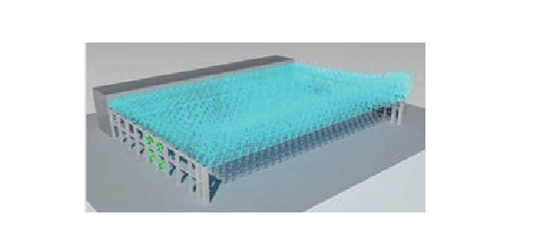
The hangar and annex building project in the north area of the maintenance and special vehicle maintenance area of the Beijing New Airport Eastern Airlines Base project faces east from the west, and consists of the hangar hall and the annex built along the entire length of the rear gable wall. Among them, the hangar hall is 15 225.61 m 2, with a plane size of 147 m×99.7 m. The plane is supported on three sides, and the side facing the apron is open. The opening side span of the gate is 147 m, the total height of the building is 39.05 m, and the elevation of the center point of the upper chord of the space frame is 22.5-37.5 m (Fig. 1).

Figure 1 Plane rendering of the hangar structure
The steel roof of the hangar is divided into two parts: the hangar hall space frame and the hangar door space frame. The hangar hall mainly adopts a 3-story obliquely placed square pyramid space frame structure with lower chord support. The main space frame size is 4.90 m×5.25 m. The height is 5.00-9.50 m, and all the nodes are welded ball nodes. The roof of the hangar door is reinforced with a 5-layer side space frame, with a total height of 15 m. Steel components include round steel pipes, welded balls, seismic bearings, purlins, etc., with a total steel consumption of 1 600 t and materials of Q355B. The minimum section of the bar is φ89 mm×4 mm, the maximum section is φ550 mm×32 mm; the welding balls are mainly hollow welding balls, the minimum specification is φ250 mm×10 mm, and the maximum specification is φ800 mm×32 mm.
2、Engineering characteristics and engineering safety protection difficulties
2.1、Engineering Features
This project has a large span (147 m), complex structure, three-sided support, one free side, a large number of components, a total of 13,048, the steel roof joints are welded hollow ball joints, and the number of hollow balls is 3,404. The door head is a 5-layer side space frame, and the upper and lower strings of the door head space frame adopt penetrating ball nodes. There are two cast steel joints on both sides of the door head, with a single piece mass of about 3 t. There are a total of 26,000 welds on site. The welding volume is large, and the welding requirements between cast steel joints and ordinary steel are high.
Other specialties were inserted into the construction in advance, and radiant heating pipes, lamps and trunkings, siphon rainwater pipes, roof primary and secondary purlins, maintenance curbs, etc. were installed on the space frame before the upgrade, with an additional mass of about 160 t, which greatly reduced the difficulty of safety protection. Avoiding the risk of subsequent high-altitude installation also enables the prefabricated construction to be well applied in this project.
2.2、Difficulties in engineering safety protection
The safety protection area of this project is large, there are many protection parts, and the highest operating point is 39.05 m from the ground. Therefore, the safety protection requirements during the construction process are high, and the construction is difficult. According to the structural form, construction method and site conditions of the space frame, a number of safety protection measures have been designed for different structural parts and different construction stages, mainly including the following points: safety protection technology for the ground assembly of the space frame in the hall, and the space frame at the door head Safety protection technology for ground assembly, installation and protection technology for supporting facilities such as radiant heating in the space frame, safety protection technology for upgrading brackets, safety protection technology for the closing part of the space frame, and safety protection technology for roof purlin and roof panel installation.
3、Main construction methods
After comprehensive consideration of structural characteristics, project progress requirements, cost control and other factors, after comparing multiple plans, the construction method of ground assembly and one-time overall lifting by computer-controlled hydraulic jacks was finally determined.
In this method, truck cranes are used to assemble part of the space frame in the hall and the space frame at the door head on the ground from the middle to both sides, and install the lifting support frame and lifting equipment, roof purlin support and main purlin and other supporting facilities at the same time, and then use computer-controlled hydraulic jacks Lift up to the design elevation as a whole at one time, then adjust the elevation of each support of the space frame, lock the lifting equipment, repair the poles, close them, and finally unload the space frame, remove the lifting equipment and support frames.
A large amount of assembly work of this method is completed on the ground, which can effectively reduce the amount of scaffolding, reduce high-altitude operations, reduce the difficulty of project safety management, realize multi-point and multi-surface flow operations, speed up the progress of ground assembly, and facilitate the control of engineering installation accuracy.
4、Construction safety protection technology
4.1、Safety protection technology for the ground assembly of part of the space frame in the hall
4.1.1、Small unit assembly safety protection technology
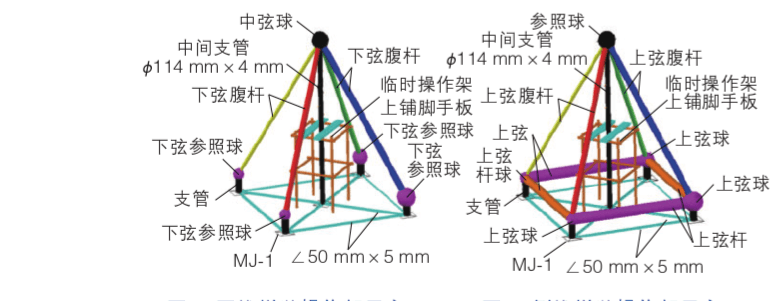
According to the site conditions, a part of the rods will be assembled into “positive triangular cones” (Fig. 2) and “inverted triangular cones” (Fig. 3) at the small assembly site, and transported back to the installation location for hoisting. This method is conducive to improving the reuse rate of on-site assembled tire frames and speeding up the construction progress.

Fig. 2 Schematic diagram of forward cone assembling operation
Fig. 3 Schematic diagram of inverted cone assembling operation
When the small-scale unit is assembled in the small-scale site, a targeted operating scaffold is set up and scaffolding boards are laid on it. The operating frame is welded with φ48 mm×3.5 mm steel pipe, with a size of 1.2 m×1.2 m and a height of 2m.
Some rods in the net frame need to be assembled into a “matchstick” shape or a “dumbbell” shape (Figure 4).

Figure 4 Schematic diagram of “matchstick” and “dumbbell” shapes
