

+86 177 5193 6871
222, Block B, Diamond International, Guozhuang Road, Xuzhou, Jiangsu, China
1、Project overview
A new stadium (see Figure 1) covers an area of approximately 54,726m and a total construction area of 67,696m, respectively. It is mainly used to hold large scale sports events and can accommodate 56,000 spectators at the same time . The main structural system is a large span cantilevered pipe truss. The entire gymnasium is a double-axis symmetrical building, which uses a steel structure to support the roof canopy. Its plane projection is ring-shaped, and the inner ring and outer ring are elliptical and circular respectively . The diameter of the outer ring is 256.8m, and the diameter of the inner ring is 208.4 and 160.6m. The truss structure is mainly composed of 88 main trusses and 4 ring trusses. The supporting devices used mainly include single diagonal braces and V-shaped supports. There are 176 steel casting nodes in the entire space frame structure. The maximum and minimum widths of the main truss are 6.8 and 2.2m respectively, the maximum and minimum cantilever spans are 42 and 10.6m respectively, and the highest elevation is 47.820m. The total weight of the steel structure used in the entire gymnasium is about 7400t, of which the main truss is made of Q355 material, and the rods are circular steel pipes with a maximum cross-sectional size of 4500×20.
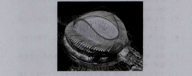
Figure 1 Schematic diagram of the gymnasium
2、Key points of construction technology for large span cantilevered pipe truss structures
Truss Segmentation and Hoisting Blocks The main truss in the gymnasium is in the shape of a 7. In order to facilitate construction, under the premise of ensuring the quality of the project, each main truss is divided into two parts: the facade wall frame section and the cantilever section. Near the outer ring support. When hoisting and subdividing, the basic principles of convenient assembly and hoisting and minimum overhead work should be followed. According to the truss segmentation, 1 facade wall frame section and 2 cantilevered sections are hoisted as a unit respectively during hoisting . Two of the overhanging sections need to be assembled on the ground first. For the supplementary installation of connecting rods between hoisting units, it needs to be completed through high-altitude operations.
The truss ground assembly should firstly set up the assembly site scientifically . It is necessary to ensure sufficient storage space for the assembled components and ensure that mechanical vehicles can pass through smoothly. The ground on the construction site is not hardened, so 600mm steel brazing can be used to fix the H-shaped steel frame platform as an assembly work platform; secondly, considering factors such as strength, stability, and versatility, the assembly tire frame should be reasonably set to ensure its form and components The matching of the shape, and ensure that the position, radian, and angle of the tire mold are consistent with the design drawings; then assemble the truss in the order of the lower chord, upper chord, web member, secondary truss and tie rod between the two plane trusses, and temporary reinforcement bars can be added to prevent The truss has a large deformation . In order to minimize the shrinkage stress caused by the welding operation, the truss welding should be completed in the order of the middle and then the four sides; after the truss is finally assembled, it needs to be restored to a free state, and it will be accepted after the measurement is accurate. . In order to reduce the assembly workload of the ground truss and save the amount of materials, the three-dimensional assembly can be carried out with the help of the model, and the assembly coordinates can be obtained as the basis for on-site operations. The tire frame used in the assembling operation is I-beam . After determining the optimal structural form, use MIDAS software to calculate its load capacity, and lay it out on site after meeting the requirements. In order to ensure the accuracy of the truss assembly, it is necessary to use a level and a total station to monitor the whole process. After the two trusses are accurately aligned, the connecting rods between the two are reinstalled.
Temporary support design
In this construction, the lattice-type standardized tire frame was selected as the temporary support tire frame. Its composition includes a base, a top beam and several standard sections . part to connect. The height of the temporary support device is relatively high, and the highest point is about 38.5m from the ground because of its poor stability . For this reason, a number of foundation piers were prefabricated with reinforced concrete structures for setting tire frame embedded parts . The specifications are 3.8mx3.8mx0. 5m. After accurately locating the laying position of the tire frame, the soil replacement method is used to improve the foundation of the construction site to enhance its strength and hardness, and then the prepared foundation pier is buried at the laying position of the tire frame, and a suitable pier is placed on it. Heavy objects are used to enhance the firmness and stability of the tire frame foundation and enhance its load capacity. The tire frame and foundation pier can be recycled for many times. After the construction of a certain area is completed, it can be dug out and used in another construction area. At the same time, use the connecting truss and double H-shaped steel to connect each independent tire frame. The connection points are respectively set in the middle and top of the tire frame, and then the cable wind rope is pulled in the other two directions to enhance the strength and stability of the tire frame.
Copyright © Xuzhou LF Engineering & Construction Co., Ltd. All Rights Reserved.

 +86-17751936871
 +86-516-8595-0258
 marketing@lfspaceframe.com


